 |

16 Jun 2006
A beam profiler is an essential tool for any laser user. Carlos Roundy describes the options available and how to pick the right profiler for your application.
Every laser user knows that they need a power or energy meter to monitor their laser's output to check that it is operating properly. However, many laser users do not appreciate the value of a laser beam profiler. The profile, in contrast to the raw power or energy, is the distribution of the intensity within the laser beam.
The ideal distribution can vary from laser to laser and from application to application. For example, many processes require the highest possible intensity. In this case, a Gaussian or TEM00 beam is ideal because it focuses to the smallest possible spot. On the other extreme, applications such as stripping paint off battleships require a uniform, large-area beam and here a flat-top beam is desired.
Different lasers naturally produce different types of beams, but each one can be optimized. Most Nd:YAG lasers are multimode at most power settings, but the profile of that multimode beam can change dramatically over time or for various settings.
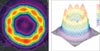
On many lasers, a change in power results in a change in beam profile. In some cases, the power density will decrease even when the total power is increased. An illustration of the value of a beam profiler is shown for the Nd:YAG laser profiles in figure 1.
In figure 1a, the laser is at a low-power setting which gives a somewhat Gaussian beam. In figure 1b, a mid-power setting produces 2.5 times more power but the peak intensity increases by only 27%. Note that the beam width increased by 31%, something that would not have shown up on a power meter. In figure 1c, the high-power setting produces 24% more power over the mid-power setting but the power density increases by only 5%. Increasing the power to the Nd:YAG flash lamps increases the laser power, but the peak power, which often does the work, may not increase as much as the total power.
Types of beam profiler
Most beam profilers fit into two technology groups. The first includes mechanical scanning slit, pinhole or knife-edge devices while the second is camera-based.
Mechanical scanning profilers give the highest resolution, especially when measuring the profile of focused spots and resolution in the range of 1 μm is possible. These profilers work by a mechanical knife-edge (pinhole or slit) crossing the laser beam in front of a single element detector. The detector reads out the signal versus time and electronics converts the time signal to a spatial one, giving the beam profile.
While mechanical profilers can measure beams to the highest resolution, they have the disadvantage that they only work for continuous-wave (CW) lasers and not pulsed sources. They also give only a two-axis profile (or with one commercial device, 7 axes) as opposed to a full 2D profile.
Camera-based profilers work by splitting off a small percentage of the beam and directing it onto a 2D camera sensor. The intensity distribution of the signal is then read from the camera and processed by computer software.
The resolution of camera-based profilers has increased dramatically over the last few years as camera pixels are now in the 4 μm range. This is a great improvement over the 10-20 μm pixels of just a few years ago.
The big advantage of camera-based products is that they profile the entire beam simultaneously and give a picture of the full 2D pattern. These profilers work with both pulsed and CW lasers, and there is a broad range of software features to fit almost every user's application.
A camera-based profiler consists of a camera to receive the laser beam, a computer and software to display the profile, and a wide variety of optics, to attenuate the beam before entering the camera (see figure 2).
Camera-based profilers
There are many camera sensor types to choose from when it comes to this type of profiler. The most common is a CCD sensor. Cameras using CCD sensors are very linear and have a high signal-to-noise ratio, both of which are essential for accurate beam width measurements. This is because low-level energy in the wings of the beam has a significant effect on measuring the beam width. Newer CCDs come with a FireWire output, which is the fastest currently available technology to interface with PCs.
CMOS sensors are also common and tend to use a USB interface, which enables easy connection to laptop computers. However, CMOS sensors are not as linear as CCDs, especially at the low intensity levels at which the suppression of the wings of the beam can cause errors in beam-width measurements. Overall, a CMOS beam profiler typically costs about €4000, versus €5000 for a CCD.
A third sensor common to beam profiling is indium gallium arsenide (InGaAs), which is used primarily for the 1-1.8 μm wavelength range. InGaAs cameras are very expensive at about €30,000. Recent replacements for InGaAs cameras, which cost in the range of €3000 to €10,000, use a phosphor that is sensitive in the 1550 nm range. However, the phosphor cameras have considerably lower resolution than the InGaAs cameras.
The next most common sensor is a pyroelectric camera, which works extremely well for wavelengths longer than 1.8 μm right into the terahertz region of 3000 μm. However, these are also expensive, in the range of €20 000, and have fairly low resolution at 100 μm pixels, with a maximum of 124 × 124. Pyroelectrics are the only commercially available camera for the terahertz region, but are not sufficiently sensitive for many applications. Pyroelectric cameras, however, are great for CO2 lasers at 10.6 μm, where there is always plenty of power.
A major issue is the use of camera-based profilers with Nd:YAG lasers. CCD or CMOS are typically used but the Nd:YAG laser wavelength often causes blooming. This blooming is sometimes, but not always, visible in the beam profile and could distort the beam-width measurements.
Beam-width measurement
Besides visualizing the laser beam, measuring the beam width is probably the next most important contribution of a beam profiler. One must know the beam width to calculate the power or energy density. The beam width is essential for calculating the divergence of the beam, which helps predict the propagation characteristics and width of the beam as it travels through space or other optical components. The width measurement is used in calculating the beam propagation factor, or M2, which has become the most standard and useful measure of the "quality" of a laser beam.
Tom Johnston, one of the early designers of beam propagation analysers, famously said that measuring the width of a laser beam is like trying to measure the width of a cotton wool ball with a caliper. Various definitions were common, such as Full Width Half Maximum (FWHM), 86% of the energy, 13.5% of the peak, 10-90 knife-edge, and others, which made the field very confusing.
However in ISO 11146 the "standard" definition for a beam width became D4σ. This is the only beam width definition that enables one to predict what width the beam will be in propagating through space. Software algor-ithms are available that enable camera-based profilers to measure the D4σ width.
Software
Commercial beam profilers tend to come with a variety of software features. The majority of companies offer the same basic features, even though the look and feel is slightly different. However, one distinguishing factor is the proper treatment of the camera offset baseline that is essential for accurate laser measurements.
One supplier holds a patent for the algor-ithms that correctly set the baseline of the camera. The problem with the baseline is that CCDs and CMOS typically have an offset to the baseline relative to zero.
If this offset is positive, the software will interpret it as wings in the laser beam and calculate a width that is too large. If the offset is negative, the beam wings are cut off by the digitizer and the measurement will be too small. By subtracting the baseline accurately and keeping components of noise that are both positive and negative in the baseline subtraction, a beam profiler can accurately measure laser beams under a much greater variety of circumstances.
Other software considerations are ease of use; speed of update of beam profile data; ability to use a number of different cameras; automatic setting of the camera electronic shutter for automatic beam attenuation; and many more. Users should select software tailored to their application.
Software to measure the beam propagation factor, M2, is also available. There are two commercial standalone M2 measuring units and a number of packages that provide semi-automatic M2 measurements.
Applications
Although scientists are well-versed in using profilers in their investigations, scientific research continues to throw up new users, uses, and applications. In medical markets, the primary use of beam profilers is still with the developers of the lasers, rather than with the users, and profilers could greatly improve the reliability of medical procedures using lasers. Materials processing has seen only minimal use of beam profilers. However, it has been shown that reliability of the processes and productivity could be greatly improved by the application of beam profilers to the lasers.
In summary, the combination of a power or energy meter with a beam profiler provides complete characterization of a laser beam. Both of these measurements are critical in making informed decisions about the status of the laser performance.
 |  |  |  |  |  |  |
| © 2026 SPIE Europe |
|