 |

06 Mar 2006
Understanding polarization, polarization control and waveplates can be a daunting task. Emily Kubacki from CVI Laser describes the how, why and what of waveplates.
Even after grasping the theory behind polarization, choosing the right polarizer or waveplate for your application can still be confusing. Different technologies, wavelengths and bandwidths all require different types and levels of polarization control, and selecting the correct component can prove critical to the outcome of the experiment.
In simple terms, polarization is the direction in which a lightwave's electric field oscillates. Because lightwaves are transverse waves, the electric field is always perpendicular to the direction of the propagation of the beam. A ray of light in which the direction of polarization varies randomly is called unpolarized.
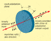
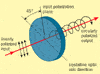
Several other polarization states exist, such as linearly polarized or plane-polarized light, which occurs when the electric field is always parallel to the x- or y-direction, or some angle in between. Birefringent materials, such as those used in waveplates and wave retarders, can be used to modify the phase of one of the directional components of the electric field, resulting in elliptically or circularly polarized light.
What is a waveplate?
A waveplate, or wave retarder, is a component that resolves a lightwave into two orthogonal linear polarization components and produces a phase shift between them. A waveplate will not change the intensity of the incident light, it will simply change its polarization state.
Most waveplates are linearly birefringent. This means that the index of refraction differs along the two principal axes (fast and slow), which affects the phase shift of the orthogonal components differently. The axis with the higher index of refraction is called the slow or extraordinary axis because light travels more slowly along that direction. The axis with the lower index is termed the fast, or ordinary, axis. Examples of birefringent materials include crystal quartz, crystal mica, calcite, cellophane paper, ice, sodium nitrate, rutile and lithium niobate - although not all of these are useful as optical components.
The amount of phase shift, or retardation, depends upon both the thickness of the material and the wavelength of the incident light. Two common components are the half waveplate and the quarter waveplate. When the difference in phase introduced between the two polarization components equals one half of a wave, the component is called a half waveplate or a λ/2 retardation plate. Similarly, or at half the thickness, a λ/4 retarder, or quarter waveplate, introduces a difference in phase equalling one-quarter of a wave.
Half waveplates rotate the polarization of linearly polarized light to twice the angle between the incident plane of polarization and the fast optical axis. These components are often used to rotate the polarization by 90° by aligning the optical axis of the waveplate at 45° to the input polarization plane. Other popular uses include rotating of circularly polarized light from right-handed (clockwise) to left-handed (counter clockwise), or vice versa. Half waveplates are often used in electro-optic modulators, continuously adjustable polarization rotators, variable laser beamsplitters and variable attenuators.
Quarter waveplates convert light between linearly and circularly polarized states. Circularly polarized light is achieved by phase shifting one component of the linear electric field by λ/4 with respect to the other orthogonal component. This is done by aligning linearly polarized light midway between the slow and fast axes of a quarter waveplate. Quarter waveplates can also be used to create linear polarization from circular input. This feature of quarter waveplates is utilized in optical isolators, electro-optic modulators, interferometers, ellipsometers, optical pumping and polarmetric imaging applications.
Waveplate options
Selecting the right waveplate for any application depends primarily on the wavelength and bandwidth of your light source. In the ultraviolet, visible and near-infrared wavelength regions, the most common waveplate is a single plane-parallel plate of crystal quartz cut with the optical axis in the plane of the polished surfaces.
These plates typically come in thicknesses ranging from 0.5 to 1 mm, making them significantly thicker than a true half wave or quarter waveplate would be. To resolve this, the waveplates are designed to retard an integer number of waves, or orders, plus the required fractional quarter and half wave retardation. Such components are called multiple-order waveplates.
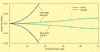
The added thickness of a multiple-order waveplate does not directly affect its optical performance. It does however have an effect on the waveplate's sensitivity to temperature and wavelength variations, making multiple-order waveplates most useful at specific wavelengths and operating temperatures. A 0.5 mm thick crystal quartz waveplate at room temperature, for example, can be used at 500 nm as a quarter waveplate (37 λ/4 waves) or at 488.2 nm as a half waveplate (19 λ/2 waves).
Crystal quartz is the most commonly used waveplate material for wavelengths between 193 and 2500 nm. In the deep ultraviolet and in the mid-infrared from 3 to 7 μm, magnesium fluoride (MgF2) has a higher transmission and is the birefringent material of choice. For applications involving infrared wavelengths greater than 10 μm, waveplates are primarily fabricated from crystals such as cadmium selenide (CdSe) and cadmium sulphide (CdS). For each of these materials and wavelength regions, the principles of retardation and birefringence are the same and the material choice is driven by the transmission properties of the crystal.
True half wave and quarter waveplates can be manufactured for applications requiring increased bandwidth, field-of-view or thermal stability. Often called true zero-order or first-order waveplates, they can be made as single plates around 100 μm thick or adhered to a thicker host substrate via optical contacting or optical cement.
Often used in DVD and telecoms applications, these very thin waveplates are ideal for use in the near-infrared as components in DWDM variable attenuators, circulators and analysers. At 1550 nm, a true zero-order half waveplate is approximately 91 μm thick and can be used off-axis to ± 8° or across a bandwidth of over ± 50 nm. A true half waveplate at 632.8 nm will only be 35 μm thick. In this case, a host window is required for structural support during manufacture and mounting to prevent breakage.
A common way to alleviate the temperature sensitivity of multiple-order waveplates, while also increasing the useful bandwidth, is with a compound zero-order waveplate. These are constructed from two multiple-order waveplates aligned with their axes crossed. Compound zero-order waveplates are designed so that the two component parts differ in thickness by the exact amount necessary to form a true zero-order waveplate with the desired fractional retardance. They can be optically contacted, cemented or air-spaced, depending on the damage threshold requirements and space constraints of the system. For example, an optically contacted zero-order waveplate designed for 1064 nm performs well over a bandwidth of about 100 nm and can withstand laser damage thresholds in excess of 10 J/cm2.
If a compound or true zero-order waveplate does not offer retardance over a wide enough wavelength band, one solution is to use an achromatic waveplate. These components are designed using two different substrate materials with compensating retardances and dispersions of retardance. The net birefringent phase shift of such a waveplate can be held constant over a 300 nm bandwidth with the right combination of materials and thicknesses.
A typical achromatic waveplate is comprised of crystal quartz and magnesium fluoride, which has a polarization purity of better than 30:1 over the entire visible wavelength region. When air-spaced and anti-reflection coated, this type of waveplate transmits more than 98% of the input light and handles laser energies of up to 2 J/cm2 making it ideal for use in spectrophotometry, optical parametric oscillators and for broadband dye and femtosecond laser systems.
One point to note however is that crystal quartz and MgF2 both have positive birefringence, making this combination highly sensitive to alignment and limiting the field-of-view. For certain applications or uncollimated beams, a less common but more appropriate material combination is to pair a crystal with negative birefringence, such as lanthium fluoride or sapphire, with the crystal quartz element.
If an application requires retardation over a wavelength range greater than an achromatic waveplate can provide, the answer is a Fresnel rhomb. Developed in 1817, these prisms use total internal reflection (TIR) to produce a phase delay between the polarization components which is both spectrally and thermally stable.
When cut at the appropriate angles, one component of linearly polarized input light is retarded by 45° at the TIR interface so that the two internal reflections produce a total phase difference of 90°, equivalent to a quarter wave of retardation, across a very broad bandwidth. Similarly, a half wave retarder is created by assembling two quarter wave rhomb prisms, either cemented, air-spaced or optical contacted. Depending on the wavelength(s) of interest, Fresnel rhombs are available in common substrate materials such as BK7 glass, fused silica, calcium fluoride and FK5.
For low-energy visible and near-infrared applications, where low dispersion or a wide field-of-view is required, polymer and liquid-crystal waveplates may be more practical. Polymers have a lower birefringence than other common waveplate materials and do not tend to be affected by changes in wavelength or angle of incidence, making them ideal for use as zero-order waveplates. They can also be layered to create achromatic waveplates with bandwidths of 200-400 nm. Polymer retarders are available in larger sizes than crystal quartz waveplates (>2 inch diameter) and are generally laminated between glass plates to improve handling and protect the polymer material.
Liquid-crystal waveplates are electronically controlled, continuously variable true zero-order retarders. Real-time control of the retardation from nearly zero to over one half wave is accomplished by applying a low AC voltage to the retarder, which comprises a liquid-crystal material layer between two environmentally sealed parallel plates. As the voltage is increased, the liquid-crystal molecules realign themselves and the effective birefringence of the material is reduced, changing the resultant retardation of the waveplate.
To select the most suitable component for any application it is important to consider all the variables, not just wavelength and cost. Bandwidth, angle of incidence, damage threshold, dispersion, operating temperature, retardation, accuracy and space constraints should each be taken into account when choosing a waveplate or other optical retarder.
 |  |  |  |  |  |  |
| © 2026 SPIE Europe |
|